Jump to content


Photo

Idea about rocket fuel


  • Please log in to reply
26 replies to this topic

#16 selwyndog

selwyndog

    Member

  • General Public Members
  • PipPip
  • 10 posts

Posted 13 February 2007 - 09:03 PM

Interesting that you can use ordinary polyester / styrene fibreglass resin. Looks like the Al is the main fuel here if the proportions are correct, as opposed to the dual purpose fuel/binder resin used with AP. Do you have a web reference for more info on this AN based formula or similar ones?


Alas no, me background is as a pure research chemist, and I used to work with polymer binding agents when I was a friction material development chemist. As you rightly said the Al is the fuel and provide most of the energy in these compositions, the binder styrene in the case is present just to stick the fuel together. Styrene/unsaturated veg oil will also undergo free radical polymerisation together to give a slightly more flexible binding agent and due to the extra hydrogen relative to styrene alone slightly more binder can be used.

#17 selwyndog

selwyndog

    Member

  • General Public Members
  • PipPip
  • 10 posts

Posted 14 February 2007 - 12:16 AM

Using the styrene binder as a fuel only the stiochiometric ratio is
ratio of NH4NO3:Styrene 100:6.5
Al only as the fuel
ratio of NH4NO3 :Al 40:9
A mixture of these two compositions will combust completely.

#18 dr thrust

dr thrust

    Pyro Forum Top Trump

  • General Public Members
  • PipPipPipPip
  • 1,408 posts

Posted 30 May 2007 - 07:46 PM

hi whats the styrene,veg oil ratio 100:5? would this stop cracking of the core in other web forums they talk about the core cracking with possible pressure build up,and failure (bang) they also talk about casting the core in sections ?mm long ,then fixing,glueing with styrene together in the tube to avoid this. would a more flexible core solve this? any rocket builders out there :blush:

#19 Give_me_APCP

Give_me_APCP

    Member

  • General Public Members
  • PipPip
  • 29 posts

Posted 06 June 2007 - 06:55 AM

Personally, if I was someone seeking a simple high Isp propellant with minimal problem areas, ammonium perchlorate is a good place to start. The problem with AN as stated, is mainly its hygroscopicness. Paraffin at lowered levels as in propellent would not infact seal the propellant of its hygroscopicness completely, though I can imagine it would help a bit. I am unfamiliar with something like paraffin working well as a binder for AN.

The amounts of fuel in AN propellants are generally so high that it makes them insensitive to detonation in a rocket motor, so the propellant actually being an explosive you would not have to worry about.

The AN is more stable and takes more heat to get it going. It requires better ignition over AP propellant. Some AN mixtures yield a brittle grain structure, and thus case design must be accounted for. If your grains are tight and seal to the liner of the motor, they will act as the case. I.E. a load bearing structure. The core will be forced to expand under pressure, and cracking may occur. This will CATO a motor. Therefore, the grains are to slightly free float in the motor, so the pressure may flow around them and equalize. This permits the case to expand, while the grains remain the same size.

AP motors using R45 (HTPB) or PBAN have much more elasticity. They become a rubber-like material. They are much more forgiving in that aspect.

And not to mention, who can resist those flames from APCP?!? A 1% CuO is sufficient for very pretty violet/blues. Brass will also work and not act as a catalyst for those colors. A bright purple is possible with brass and strontium nitrate. >7% Al will give nice bright white flames like the space shuttle. There are just tons of known formulas for AP propellent out there, so there is much to play with.

Selwyndog, not to contradict your info, but where are you deriving these "exhaust gas velocities" from?

2200m/s is over 7200 feet/sec. Nowhere in a conventional design rocket motor do gas velocities reach near 7200fps, unless when possibly viewed on a molecular level near the reaction zone.

Gas velocities are mainly subsonic internally through the core, unless a nozzle throat exceedingly larger than the core diameter is used. They converge into the throat and are accelerated to supersonic velocities out of the throat while passing through the divergence portion of the nozzle.

If you reached gas velocities well into the supersonic range internally, your cores would instantly CATO due to an extremely high rate of core erosion.

#20 dr thrust

dr thrust

    Pyro Forum Top Trump

  • General Public Members
  • PipPipPipPip
  • 1,408 posts

Posted 19 August 2007 - 01:45 PM

hi does anybody know the whistle/bp hybrid formula and how to charge the case :) ,not ready for it yet but just "collecting info,ho yeah ive asked before but no joy!what part does silicone (II) play in blue strobeing RP,ho yeah almost forgot whats THE(II) stand for?

#21 Andrew

Andrew

    Rocket Scientist, no really, I am!

  • General Public Members
  • PipPipPip
  • 603 posts

Posted 19 August 2007 - 07:10 PM

2200m/s is over 7200 feet/sec. Nowhere in a conventional design rocket motor do gas velocities reach near 7200fps, unless when possibly viewed on a molecular level near the reaction zone.


I beg to differ. The HTP monoprop miniaturised thruster for use on nano-satellites that I've been researching and developing has reached a specific impulse of over 120s in tests. It's effective exhaust velocity was over 1200ms-1, (about Mach 3.5 at sea level).

Recent alterations to the existing design, which is what I'm testing at present (a simple alteration which I can't divulge as it is being patented), have led to an Isp of around 305s, which means that the effective exhaust velocity is pretty much 3km/s (about Mach 8.8 at sea level, in fact this is not supersonic flow, it is what is called hypersonic flow). And I must say that it has NO nozzle, it is just a convergent throat. The expansion as the gas flow leaves the throat accelerates it to a supersonic flow. And these tests are at sea level where propellant efficiency is reduced.

I know of solid rocket technology reaching specific impulses of well over 250s at sea level, I'm sure there are some exotic ones that push 300s. But I can say for certain that there are a lot of solid propellant rockets out there that have effective exhaust velocities over 2.3km/s (about Mach 6.8 at sea level, again all the way to hypersonic flow).


Gas velocities are mainly subsonic internally through the core, unless a nozzle throat exceedingly larger than the core diameter is used.


If the "nozzle throat" is wider than the grain then it is not the throat.


Simple rocket lesson.
1. Gas flow in the chamber = Subsonic (always with no exceptions).
2. Subsonic flow is accelerated by a converging section.
3. Gas flow is transonic at the throat.

As long as the throat is smaller than a threshold diameter the flow will always and only have a Mach number of 1.
If the throat is smaller than it needs to be, the Mach number is still 1 but the pressure inside the chamber increases.
With an increased chamber pressure the mass flow area density through the throat increases, that's all.

4. Supersonic flow is accelerated by a diverging section.

The exhaust gases are accelerated by the expanding nozzle.


The flow velocity can only ever reach Mach 1 at the throat. There are no exceptions, it is bound by the laws of physics. There is no such thing as supersonic flow within the chamber (or inside the grain); if it is supersonic it is not in the chamber. With no converging section (throat) the exhaust gas flow cannot react Mach 1 and thus had no chance of be accelerated further by any diverging section.

For any given throat diameter, as you increase the mass flow rate (not only this as it also depends of things like molecular weight), the thrust increases. When you reach the threshold mass flow rate for that throat and exhaust product, you get a real kick in thrust (and propellant efficiency). This phenomena is observable in the real world to any lay person. Have you ever seen a firework rocket just after the initial ignition? It starts to rise and then (as the pressure inside increased past the required level), it really accelerates away. This delay is the mass flow rate building up past the required amount. This is why all "real" rockets are held on the ground for a few seconds before they are let loose. If you ever watch a shuttle launch there are a few seconds of "burn up" time before the clamps fall away and the shuttle moves off.

Edited by Andrew, 20 August 2007 - 08:08 PM.


#22 pyrotrev

pyrotrev

    Pyro Forum Top Trump

  • UKPS Members
  • 1,112 posts

Posted 19 August 2007 - 11:06 PM

Thanks for that Andrew, that's really interesting. Do different nozzle profiles influence the exhaust acceleration?
Trying to do something very beautiful but very dangerous very safely....

#23 Andrew

Andrew

    Rocket Scientist, no really, I am!

  • General Public Members
  • PipPipPip
  • 603 posts

Posted 20 August 2007 - 10:25 AM

Thanks for that Andrew, that's really interesting. Do different nozzle profiles influence the exhaust acceleration?


They do, but first this is a CFD (computational fluid dynamics) model of the nozzle on the work prior to mine conducted by the now Dr Sarah Barley. The image credit is as follows:

Barley, S. 2006. Micro-Chemical Monopropellant Thruster. Final Report for contract 043022. Surrey Space Centre.

Posted Image

The image may have to come down, but the entire research is kind of in the public domain.

This model uses a nozzle half angle of 15°. Note that the flow velocity is transonic across the narrowest part of the throat. The colour chart on the left is in m/s if you cannot see the finer print.

The light blue that hugs the nozzle on the way out is what is called the boundary layer. For thrusters the size we are developing boundary layers become a significant problem. Basically you cannot have supersonic flow over a surface; the heterogeneous interface causes a boundary layer in the flow. This is where the flow is subsonic over the nozzle surface. This happens in ALL nozzles. The only reason it is a problem, is because at these sizes it narrows the effective nozzle, to put it into perspective the throat on these thrusters is half a millimetre across. On amateur pyro rockets this IS REALLY unheard of. For pyro stuff you do not need to worry about boundary layers.

You may also notice that the flow accelerates further, after it leaves the nozzle!. On the top right and bottom right you can see the cross section of what is a ring of flow that is accelerated even more as it expands after leaving the nozzle. This is a really interesting result, yeah! This brings me onto the really importance of the the nozzle.

I wont go over your head and put in a load of mathematics, but instead I'll explain the result. To have the most efficient nozzle, we look at what is called expansion. In the image above the flow is underexpanded; but that is because it is in vacuum and you can never fully expand a flow into low ambient pressure. Basically the most efficient nozzle expands the flow so that the exit pressure is EQUAL to the pressure of the atmosphere. It the exit pressure is lower than the local atmosphere, you have overexpanded the flow and if the exit pressure is higher than the local atmosphere you have underexpanded the flow. Both give rise to losses and thus inefficiency. In launch vehicle design the nozzle is engineered to be correctly expanded about 2 3rds of the way up for that stage.

If you have ever seen a launch, you would have noticed that the exhaust at sea level gets compressed even before leaving the nozzle and forms visible cones (these are shock waves). The flow is overexpanded and the higher atmospheric pressure compresses the flow. This is an image of a shuttle engine test at sea level.

Posted Image

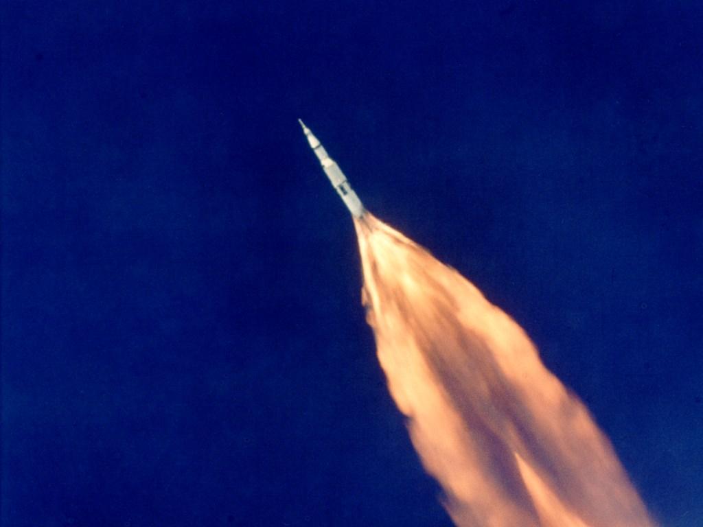
You would have also noticed that high up (lower atmospheric pressure), the exhaust plumes out sideways upon leaving the nozzle Below is a Saturn rocket being tested. It's the best image of underexpanded flow that I could find. I know that there are some fantastic ones but google is crap!!!

Posted Image


For us amateurs making rocket at will only ever experience sea level pressure we should design our nozzles accordingly. For this you need to be slightly mathematically minded to do the calculations, I can post the necessary formulae if you like. The half angle and geometry (profile) play an important role as well. For most of our applications a 15°-25° half angle and a straight cone are acceptable. The half angle you select really depends on what exit velocity you expect at that point, a faster exhaust flow needs to be expanded slower (smaller half angle). That is why the big nozzles are sort of bell shaped (approximately parabolic in profile); the slower flow just downstream of the throat is expanded faster and as it accelerates the flow is expanded slower (the half angle gets smaller). It'll be pretty difficult to tailor nozzle geometry for a small BP rocket, so for BP stick with 20°ish and just calculate the exit area and appropriate throat diameter, for higher Isp propellants use a lower half angle 15°ish.

Edited by Andrew, 20 August 2007 - 10:26 AM.


#24 pyrotrev

pyrotrev

    Pyro Forum Top Trump

  • UKPS Members
  • 1,112 posts

Posted 25 August 2007 - 06:48 PM

This is really interesting stuff :P are there any rocketry books written at this kind of level with explanations as understandable as yours?
Trying to do something very beautiful but very dangerous very safely....

#25 Andrew

Andrew

    Rocket Scientist, no really, I am!

  • General Public Members
  • PipPipPip
  • 603 posts

Posted 25 August 2007 - 09:24 PM

Level is a very relative thing! It's almost impossible for me to recommend books about rocketry because, although there are loads covering all levels, my exposure has been to the higher end stuff. I'm going to look at one of my books to see if it is suitable, and post details here if it is.

#26 FrankRizzo

FrankRizzo

    Member

  • General Public Members
  • PipPip
  • 68 posts

Posted 26 August 2007 - 10:01 PM

Thank you for that wonderful post! So, an under-expanded flow causes the exhaust gases to basically slam into the cooler air below and splatter out to the sides like it was hitting a solid cone, whereas the over-expanded flow is so low in pressure that the surrounding atmosphere constricts it down from the sides? Would you mind posting a picture of an ideal gas plume exiting a test nozzle?

#27 Andrew

Andrew

    Rocket Scientist, no really, I am!

  • General Public Members
  • PipPipPip
  • 603 posts

Posted 28 August 2007 - 02:57 AM

That's basically it. You have to remember that the faster a flow is, the lower the pressure. This is the real factor, pressure.

Posted Image

Properly expanded if not a little overexpanded (@ sea level) pulsed Oxygen/Kerosene (I think) thruster. But you get the point. Nice straight exhaust = efficient. Pulsed because the injector is not doing it's job properly or it does not have one, or the propellant feed pressure is too low.

Posted Image

Another example of properly expanded flow-ish.

Edited by Andrew, 28 August 2007 - 03:00 AM.


0 user(s) are reading this topic

0 members, 0 guests, 0 anonymous users