Jump to content


Photo

Firing system problem


  • Please log in to reply
62 replies to this topic

#46 PyroCreationZ

PyroCreationZ

    Member

  • General Public Members
  • PipPip
  • 105 posts

Posted 27 January 2010 - 04:46 PM

The meter is a device I would NOT run off a series resistor, though it might work it might also not work well.

A suitable 5v regulator would be a three terminal chip possibly a 7805 or a 7905 and which one depends on whether you need a common positive or a common negative supply.


Ok, so I didn't make it in time for NYE :(
Though I had a good (hand lit) display :)
Now I am working on the firing system again (without a deadline now :) ) and was wondering if you could help me out?
There is one more thing I'd like to change about my system and that is getting the voltage meter to work off my 12V battery.
Since I will be mounting the panel (it's not meant to be opened unless a battery would die) I don't want the 4x AA battery holder in my system and therfor I'd like your help on that 5V regulator.
That 7805 / 7905 you mentioned, how would I have to connect this? I am using common negative.
I would really appreciate if you (or someone else) could explain me or draw a little schematic how to connect it to my voltage meter.
Once I know this, I can finish my system.

Thanks in advance!

EDIT: Just looked at the datasheet CNH provided (link) and if I understand correctly I just have to get the right regulator with 5V output.
To connect: +12V to pin 1 (input), -12V to pin 2 (gnd) and then from pin 3 (output) to +5V from voltage meter, from pin 2 (gnd) to gnd from the voltage meter.
Is that correct?
Also, those regulator types/numbers (7805 / 7905), are those the same in every country or brand?
Being a foreigner I can go to the electronics store and ask for a voltage regulator with that number, right?

Edited by PyroCreationZ, 27 January 2010 - 10:21 PM.

YouTube account.


#47 pyrotrev

pyrotrev

    Pyro Forum Top Trump

  • UKPS Members
  • 1,112 posts

Posted 27 January 2010 - 07:52 PM

Almost, though I think pin 2 should be going to ground not -12V perhaps? Remember the 7805 regulator develops a regulated output voltage with respect to this pin, so if it was connected to -12V you'd get an output of -7V ref. ground. Another thing you must do is connect capacitors between input and ground and output and ground (i.e. pin 1...2 and pin 3...2) - 220nF/25V ceramic types should be fine, or alternatively 10uF/25V low ESR electrolytics (make sure the -ve terminal is to ground). Without these the regulator may go unstable and your meter read strange values!
Trying to do something very beautiful but very dangerous very safely....

#48 PyroCreationZ

PyroCreationZ

    Member

  • General Public Members
  • PipPip
  • 105 posts

Posted 27 January 2010 - 10:22 PM

I searched for a diagram of the 7805. I found one with two capacitors connected.
I edited the image for my application. Is this correct?
Help is much appreciated ;)

Posted Image

Almost, though I think pin 2 should be going to ground not -12V perhaps? Remember the 7805 regulator develops a regulated output voltage with respect to this pin, so if it was connected to -12V you'd get an output of -7V ref. ground. Another thing you must do is connect capacitors between input and ground and output and ground (i.e. pin 1...2 and pin 3...2) - 220nF/25V ceramic types should be fine, or alternatively 10uF/25V low ESR electrolytics (make sure the -ve terminal is to ground). Without these the regulator may go unstable and your meter read strange values!


Pin 2 would be connected to GND but -12V is GND, atleast that's how I meant it :)

Edited by PyroCreationZ, 27 January 2010 - 10:25 PM.

YouTube account.


#49 mike_au

mike_au

    Member

  • General Public Members
  • PipPip
  • 54 posts

Posted 28 January 2010 - 12:32 AM

I searched for a diagram of the 7805. I found one with two capacitors connected.
I edited the image for my application. Is this correct?
Help is much appreciated ;)

Posted Image


Pin 2 would be connected to GND but -12V is GND, atleast that's how I meant it :)


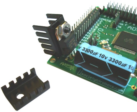
Looks good. While you are are buying the 7805, grab a clip on heatsink. You probably don't need it but they cost about $0.20 and it is always better to err on the safe side.

GND is by definition 0V everything else is measured relative to GND. If you have +12V and -12V the voltage across the two is 24V.

#50 PyroCreationZ

PyroCreationZ

    Member

  • General Public Members
  • PipPip
  • 105 posts

Posted 28 January 2010 - 07:25 AM

Looks good. While you are are buying the 7805, grab a clip on heatsink. You probably don't need it but they cost about $0.20 and it is always better to err on the safe side.

GND is by definition 0V everything else is measured relative to GND. If you have +12V and -12V the voltage across the two is 24V.


Ok, thx. I'll go buy that 7805 today or tomorrow. Yeah I stated it wrong... should be GND instead of -12V :)
I have a small heatsink but it IS small. Depends on how hot it will get but what size heatsink would you recommand or would the one I have be good enough?
12V being brought down to 5V will probably make the regulator quite hot, right?
(EDIT: It's higher current that causes it to heat up. My meter only uses 50-60mA so it won't have to be a big heatsink.)

The one I have is this:
Posted Image

Edited by PyroCreationZ, 28 January 2010 - 11:07 AM.

YouTube account.


#51 PyroCreationZ

PyroCreationZ

    Member

  • General Public Members
  • PipPip
  • 105 posts

Posted 28 January 2010 - 12:54 PM

Hmm apparently this can't be done.
I've also asked this in an electronics forum and they say if I would do it this way my readouts would be completely wrong.
The voltage from the meter has to be completely seperated from the voltage that needs to be measured.
Now I will have to use batteries on top of my system just to get the meter working :(
This is not what I had in mind...
There are two other ways they say, one with capacitors but that's kinda difficult and the other way is with a 555, a small 1:1 transformer and a rectifier but that seems to be difficult for me as I don't know very much about electronics.
Damn :(

YouTube account.


#52 pyrotrev

pyrotrev

    Pyro Forum Top Trump

  • UKPS Members
  • 1,112 posts

Posted 28 January 2010 - 01:40 PM

Hmm apparently this can't be done.
I've also asked this in an electronics forum and they say if I would do it this way my readouts would be completely wrong.
The voltage from the meter has to be completely seperated from the voltage that needs to be measured.

This is not necessarily true - although some meters have a problem with measuring a voltage close to their own ground others are OK e.g. this one I used on our system: www.lascarelectronics.com/pdf-usb-datalogging/data-logger0282407001208332584.pdf . Without a full data sheet it's not easy to tell what yours will do, maybe the easiest way is to try it?
Trying to do something very beautiful but very dangerous very safely....

#53 PyroCreationZ

PyroCreationZ

    Member

  • General Public Members
  • PipPip
  • 105 posts

Posted 28 January 2010 - 01:52 PM

This is not necessarily true - although some meters have a problem with measuring a voltage close to their own ground others are OK e.g. this one I used on our system: www.lascarelectronics.com/pdf-usb-datalogging/data-logger0282407001208332584.pdf . Without a full data sheet it's not easy to tell what yours will do, maybe the easiest way is to try it?


The only thing there is, is basic info: link
An actual detailed data sheet doesn't seem to be available on this one.
Well, I'd like to give it a try but the people on that forum said the Velleman kits, etc. often have problems when they're close to their own ground.
Anyway, I only need like 3 parts so it's worth the shot I guess.

YouTube account.


#54 PyroCreationZ

PyroCreationZ

    Member

  • General Public Members
  • PipPip
  • 105 posts

Posted 28 January 2010 - 08:54 PM

Hmm I've been thinking. If I have two batteries to make 24V, then I have two negatives as well.
So if they're right about the voltage regulator not being able to be on the same ground then I could do it as follows (I think):
Posted Image
This way the V-meter's GND is completely seperated from the voltage regulator's GND, correct?

Edited by PyroCreationZ, 28 January 2010 - 08:55 PM.

YouTube account.


#55 pyromaniac303

pyromaniac303

    Member

  • UKPS Members
  • 632 posts

Posted 29 January 2010 - 01:27 AM

So if they're right about the voltage regulator not being able to be on the same ground then I could do it as follows (I think)


This would actually give you 17V acros your meter, probably destroying it as you are grounding the regulator to the centre of the battery (either +12V or 0V depending on your perspective) and the meter to 0V or -12V. The regulator uses the middle pin, usually marked 'ref' as a reference point. As a general rule, whatever voltage this pin is at, the output of the regulator will be 5 volts higher.

Just because you may call one end of the battery + and the other -, does not mean that all the - pins are at zero volts. For instance in this arrangement of 12V cells:

voltage_upload_UKPS.GIF

Point A is at the highest potential (voltage) with respect to all the other points. With respect to B it is 12V, with respect to C 24V and D 36V. However measuring D with respect to C would give -12V, even though the terminals of all the batteries may be marked '-' it does not automatically mean they're going to be 0V.

Sorry for the long and complicated explanation.

I also doubt that using the same ground as what you are measuring will make a great difference to its performance, unless you're wanting to measure into the millivolt range. Is it purely as a battery level indicator?
You can never have a long enough fuse...

#56 PyroCreationZ

PyroCreationZ

    Member

  • General Public Members
  • PipPip
  • 105 posts

Posted 29 January 2010 - 08:02 AM

Thx for that clarification pyromaniac.
The voltage meter is purely used as a battery level indication ,yes.

When I measure at the center of the batteries I get a higher voltage like pyromaniac said so can't do it like this.
I tried the original idea and there is in fact an incorrect measurement of about 0.5V wich is not that bad...
I still have to add the capacitors so it might improve as one of them is used for stability.
Then there is also a potentiometer used to adjust the readout.
I can change this untill it matches the correct voltage but don't know if this will effect the measurement if battery voltages are getting low(er).

My batteries will be charged seperatly (selectable with a switch) with a 12VDC charger however if I add another switch I could measure total voltage + each battery seperatly.
What would you guys do?
Total power (24V) only? Or add the option of reading out each battery seperatly as well?

Edited by PyroCreationZ, 30 January 2010 - 01:49 PM.

YouTube account.


#57 pyrotrev

pyrotrev

    Pyro Forum Top Trump

  • UKPS Members
  • 1,112 posts

Posted 06 February 2010 - 04:41 PM

If you're only using it for battery level, I can't see that not being able to measure close to 0V is much of a problem - if the battery is that low, you'll have other problems like it not working :( - certainly worth a try!
Trying to do something very beautiful but very dangerous very safely....

#58 Arthur Brown

Arthur Brown

    General member

  • UKPS Members
  • 2,923 posts

Posted 06 February 2010 - 05:21 PM

The simple answer to the dilemma of common negative and near to common errors is an isolated DC-DC converter Traco do one which is 24v in and 5v out and will supply 1 watt From RS in the UK it's £6.50 ish it's a simpler and more effective solution than anything else. Go ferret through electronics suppliers in your area

Into rswww.com (no www!) put 1896795 and have a look.

RS Stock No. 189-6975 Manufacturer Traco Manufacturers Part No. TME 2405S
http://www.movember.com/uk/home/

Keep mannequins and watermelons away from fireworks..they always get hurt..

#59 Arthur Brown

Arthur Brown

    General member

  • UKPS Members
  • 2,923 posts

Posted 06 February 2010 - 06:53 PM

The answer to the 24v charger requirement can come from
RS Stock No. 543-8040 Manufacturer Recom Manufacturers Part No. REC5-2415DRWZ/H1/A

It's a dc - dc converter with 15 - 0 - 15 volts at 180mA that runs off 12 - 24vDC so you can fit it with a car lighter plug and charge a 24v battery if you sort out the voltage regulation. (A 24v battery needs 26.5 -28v to charge,)
http://www.movember.com/uk/home/

Keep mannequins and watermelons away from fireworks..they always get hurt..

#60 CCH Concepts

CCH Concepts

    Pyro Forum Regular

  • General Public Members
  • PipPipPip
  • 597 posts

Posted 15 February 2010 - 05:45 PM

what they were mentioned with the 555 timer and transformer this is a inverter or DC-DC converter. usually its a smaller voltage say 9v producing a higher voltage say 12v.

one example of this would be a stun gun, with a 9v battery producing 50,000 volts.

now in their application its 12v producing 12v and then regulate it down to 5v, the idea being to electrically isolate the battery from the meter using the transformer. by isolating the this supply from the battery it means that a change in the batteries voltage doesn’t affect the supply to the volt meter.

now this doesn’t have to be as complicated as it sounds, with a little searching you should be able to find this all done in one package.


0 user(s) are reading this topic

0 members, 0 guests, 0 anonymous users