

D-I-Y WASP Shell Pasting Machine?
Started by PyroSam, Jul 06 2012 09:38 AM
153 replies to this topic
#121

PyroSam
-
- General Public Members
-

- 67 posts
Member
Posted 13 November 2012 - 11:38 PM
Here are the specs on the ball transfer the WASP Stinger uses.
#122
PyroSam
-
- General Public Members
-
- 67 posts
Member
Posted 13 November 2012 - 11:41 PM
Our WASP owner had time to do some measurements, yes, it's a 1-1/4" ball and after the flange is cut down they are mounted on 1-1/2" centers.
#123
Barnsley-Bill
-

- General Public Members
-
- 29 posts
Member
Posted 15 November 2012 - 02:27 PM
My wheels came today and the + the stepper bee + but the postage on the wheels was expencive $70 then a £27 import/VAT charge' robbing git's.
so Hopefully I should be able to start making one this weekend/next week .
.
so Hopefully I should be able to start making one this weekend/next week
.
#124
Barnsley-Bill
-
- General Public Members
-
- 29 posts
Member
Posted 19 November 2012 - 02:46 PM
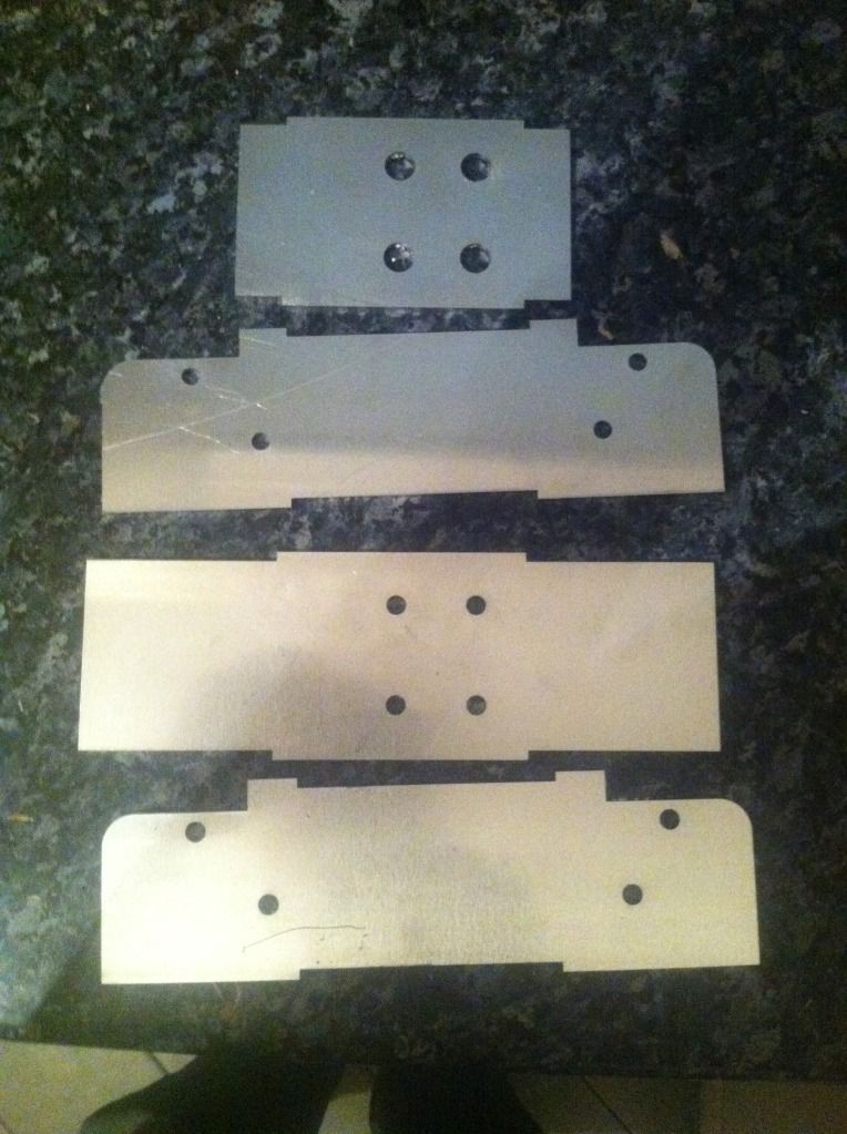
I made a start making mine, but the box section was too small for the t-slot frame so I drew up a cad file for my mate to cut some 4mm aluminum plates so I can tig weld them in to a box.
He cut me some motor plates for the NEMA 34 motors, so once I have the plates back form my mate I can weld them all together.
I also made I shaft for the drive wheels out of aluminum round bar, I've just to drill it for the motor shaft and the grub screws.
I have the power supply and the stepper bee + and the software is being worked on, so all I need to do is make the top arm and bearing brackets then I should be ready to try it.
He cut me some motor plates for the NEMA 34 motors, so once I have the plates back form my mate I can weld them all together.
I also made I shaft for the drive wheels out of aluminum round bar, I've just to drill it for the motor shaft and the grub screws.
I have the power supply and the stepper bee + and the software is being worked on, so all I need to do is make the top arm and bearing brackets then I should be ready to try it
.
#125
Barnsley-Bill
-
- General Public Members
-
- 29 posts
Member
Posted 19 November 2012 - 09:52 PM
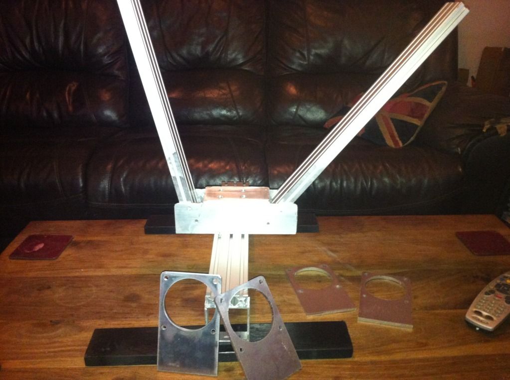
My mate dropped these off tonight jigsaw plates to make the centre spine section, enough for 4 units made out of 3mm aluminum once welded and bolted to the upright arms they should be solid enough' if not I'll get some more cut in 6mm.
#126
PyroSam
-
- General Public Members
-
- 67 posts
Member
Posted 20 November 2012 - 01:29 AM
We need a facebook-eque "Like" button!
The spine will be fine, the Mini just uses two plates on the sides and that's it.
The spine will be fine, the Mini just uses two plates on the sides and that's it.
#127
Barnsley-Bill
-
- General Public Members
-
- 29 posts
Member
Posted 20 November 2012 - 03:06 PM
Yea I think they will be up to the job too, I've dropped two off at my local engineering firm to weld up together with the motor plates and once there done I can start to build it
#128
Peret
-

- UKPS Members
-

- 213 posts
Pyro Forum Regular
Posted 20 November 2012 - 09:25 PM
I haven't been paying attention to this thread lately, so have a few points to catch up on.
If you use a narrow drive roller like the finned rollers illustrated, you will have to make the motor positions adjustable for different shell sizes. Of course this is possible, but it makes the mechanical construction more complicated, and when you move the motors you have to be careful that the positions are exactly symmetical. Using wider rollers means this uncertainty is taken care of once and for all when you build it. You don't particularly need a soft surface, just one that doesn't slip.
Just because it says in a stepper motor spec that it runs at 4V, or whatever, doesn't mean you can run them at 4V or dispense with the series resistors. They would work, but would have no torque at higher speeds. The reason for this is that driving stepper motors involves switching current on and off into inductive loads, and inductors have a time constant. That's to say, the current doesn't rise immediately to its limiting value, but rises exponentially with a time constant of L/R (inductance over resistance). Torque is proportional to current. So when you want it to turn fast and the steps are short, you have to adjust that L/R time constant so that the current rises to an adequate amount within the short time allowed, otherwise you have no torque. Since you can't reduce the L, you can only do it by having a larger R. That's why you typically see a motor rated for 4V, driven from 24V with huge smoking hot resistors in series. These days there are specialist stepper driver chips available that drive the motor with constant current - constant current equals infinite series resistance, within the working range - and since they behave like switching regulators they don't get hot.
More info here: http://www.allegromi...or-Drivers.aspx
#129
Barnsley-Bill
-
- General Public Members
-
- 29 posts
Member
Posted 20 November 2012 - 10:45 PM
I think were all going for the same rollers that's on the WASP Peret, well I am and thanks for the link there's some good reading on that site.
the stepper bee + uses Intelligent MOSFETs so i think it should be upto the job plus the motors I have run off a 3.78v power supply so I went with a 5v 20A power supply and i might get away without any limit resistors especially if the
motor does not spend too much time stationary.
the stepper bee + uses Intelligent MOSFETs so i think it should be upto the job plus the motors I have run off a 3.78v power supply so I went with a 5v 20A power supply and i might get away without any limit resistors especially if the
motor does not spend too much time stationary.
#130
Barnsley-Bill
-
- General Public Members
-
- 29 posts
Member
Posted 22 November 2012 - 01:23 AM
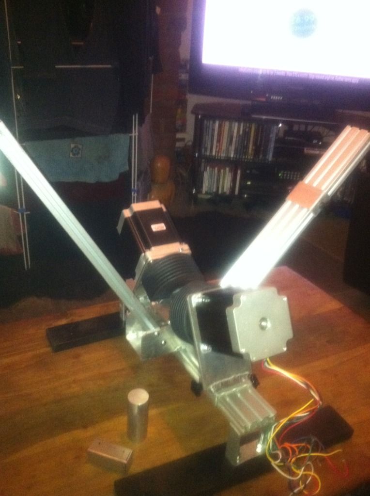
New center spine works well and motor mounts fitted with support brace as the motors are a bit on the heavy side.
The round bar is for the motor shaft and drive wheel and the square block is for the top arm hinge.
The round bar is for the motor shaft and drive wheel and the square block is for the top arm hinge.
#131
PyroSam
-
- General Public Members
-
- 67 posts
Member
Posted 22 November 2012 - 07:10 AM
Hi Peret, welcome back!
The Fixtureworks drive rollers are 1.98" wide, the fabricated ones you suggested were 2" wide so I'm thinking they are an appropriate sub. They do make 2" diameter by 1.98 wide rollers which I really did consider using but since I'm using 570 oz/in motors I figured the 4" would be ok. If not I'll step down to the 2" or have some made. I'm really trying to avoid having anything made though, trying to make it an off the shelf or fabbed with common tools kinda project.
The Fixtureworks drive rollers are 1.98" wide, the fabricated ones you suggested were 2" wide so I'm thinking they are an appropriate sub. They do make 2" diameter by 1.98 wide rollers which I really did consider using but since I'm using 570 oz/in motors I figured the 4" would be ok. If not I'll step down to the 2" or have some made. I'm really trying to avoid having anything made though, trying to make it an off the shelf or fabbed with common tools kinda project.
#132
Pyro.1
-

- General Public Members
-
- 100 posts
Member
Posted 22 November 2012 - 09:09 PM
Bill thats looking great so far,well done.
i was wondering when we can book some pasting time, barnsley isnt too far.
Paul.
i was wondering when we can book some pasting time, barnsley isnt too far.
Paul.
2KNO3(s) + 3C(s) + S(s) -----> N2(g) + 3CO2(g) + K2S(s)
#133
Barnsley-Bill
-
- General Public Members
-
- 29 posts
Member
Posted 22 November 2012 - 09:19 PM
as soon as it's finished lol, I have some spare parts if anyone wants some
#135
Barnsley-Bill
-
- General Public Members
-
- 29 posts
Member
Posted 24 November 2012 - 01:09 AM
Thanks mate, it even shows the make of the controler board from Peter Norberg the SD4DEU http://www.stepperbo...prod11-SD4D.htm.


0 user(s) are reading this topic
0 members, 0 guests, 0 anonymous users

